Quite some time ago, we published an article by Bill Ortyn on installing a third water tank. Recently, Bruce Stanley, Fantastic Lady (Hull 1084), has updated that installation. What follows is a blend of Bill’s original instructions with Bruce’s updates and fantastic photos.
Summary
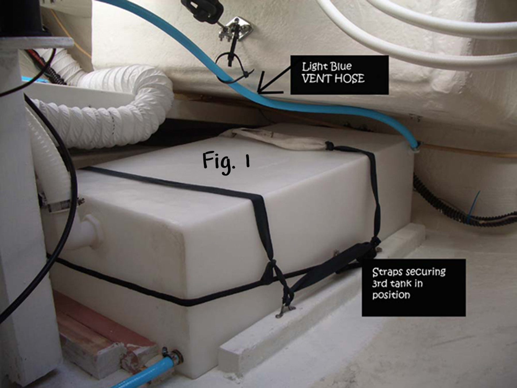
The fresh water carrying capacity of the C320 can be increased by nearly 50% by adding an extra twenty gallon fresh water tank in the lazarette behind the steering quadrant as shown in Figure 1. The installation involves four tasks and was performed in about 6 days spread over 2 weeks. This might be cut to 4 days with good planning and a helper. The four tasks include:
- changing vent fitting location on the tank
- site prep & mounting the tank
- connecting fill line & vent line
- adding shutoff valve & connecting to pump
The cost for this modification (in Sydney) was approximately $400 in US dollars. A bill of materials with cost, quantity and part descriptions is provided at the end of the article.
1. Changing Vent Fitting Location on the Tank
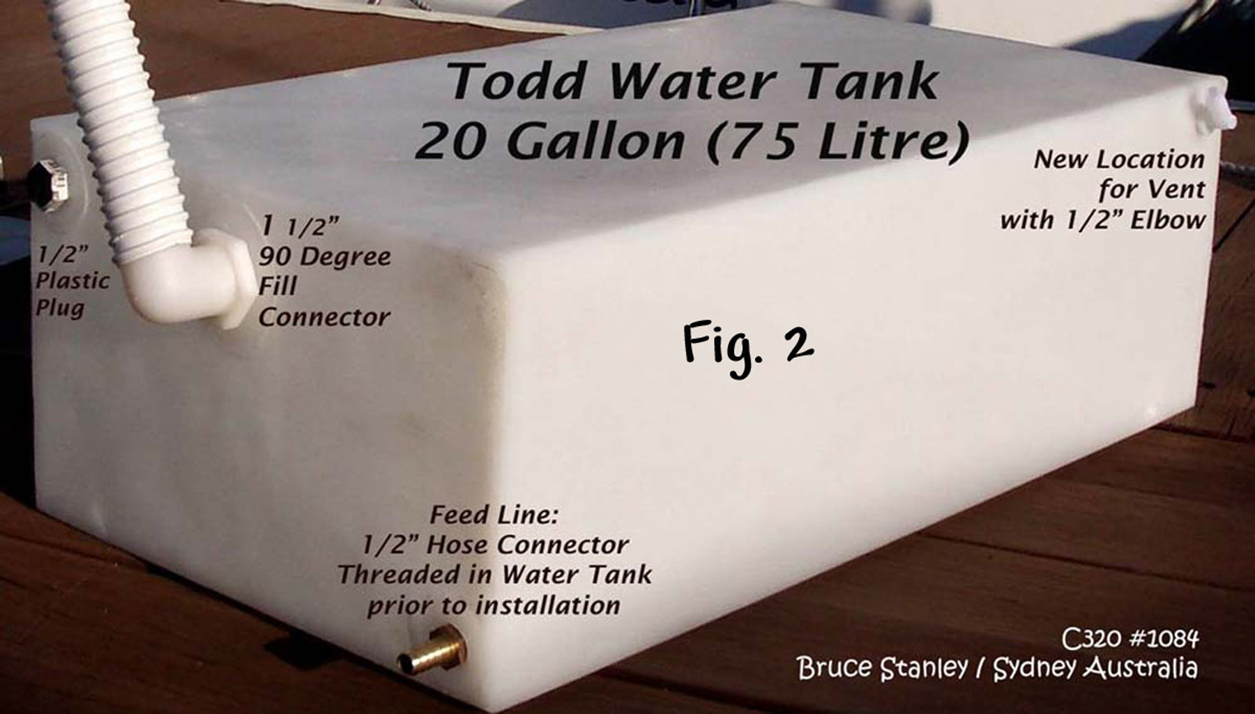
The factory vent fitting on the Todd tank is not optimally located for the C320 installation. When installed flat on the hull, the rear end of the tank will be canted upward. This orientation mispositions the existing vent hole, which in turn will limit the fill capacity of the new tank to approximately 12 gallons. To allow for a complete fill, the vent hole must be moved to the rear of the tank. Todd sells fitting relocation kits for this purpose for about $30 dollars (P/N 93-2218). If you are adventurous and want to save the additional cost, a standard brass fitting or plug may be used in a self-tapping mode to accomplish the same goal. First, a pilot hole about 1/16 inch smaller than the OD of the ½ ” NPT pipe thread is drilled into the side wall (at the rear) near the top of the tank as shown in Figure 2. The fitting should be located as high and aft as possible to maximize fill volume. The brass fitting or plug is inserted into the hole and turned clockwise while applying significant downward force. (The procedure must be performed while the tank is out of the boat, lying on its side and easily accessible.) The pipe threads on the brass fitting will cut new threads into the hole and provide a secure fitting for the vent. It is critical to drill the pilot hole undersize, so that the brass tapping tool cuts enough polyethylene to make good threads. After the threads are cut, the brass fitting is removed and the plastic elbow may be installed. The old vent hole can be plugged with the part specified in the bill of materials. Note: Several wraps of teflon tape should be applied on all threaded surfaces to prevent leakage. One advantage of the Todd Fitting Relocation Kit is that it also includes an access port which is handy for tank cleaning.
2. Site Prep & Mounting Tank
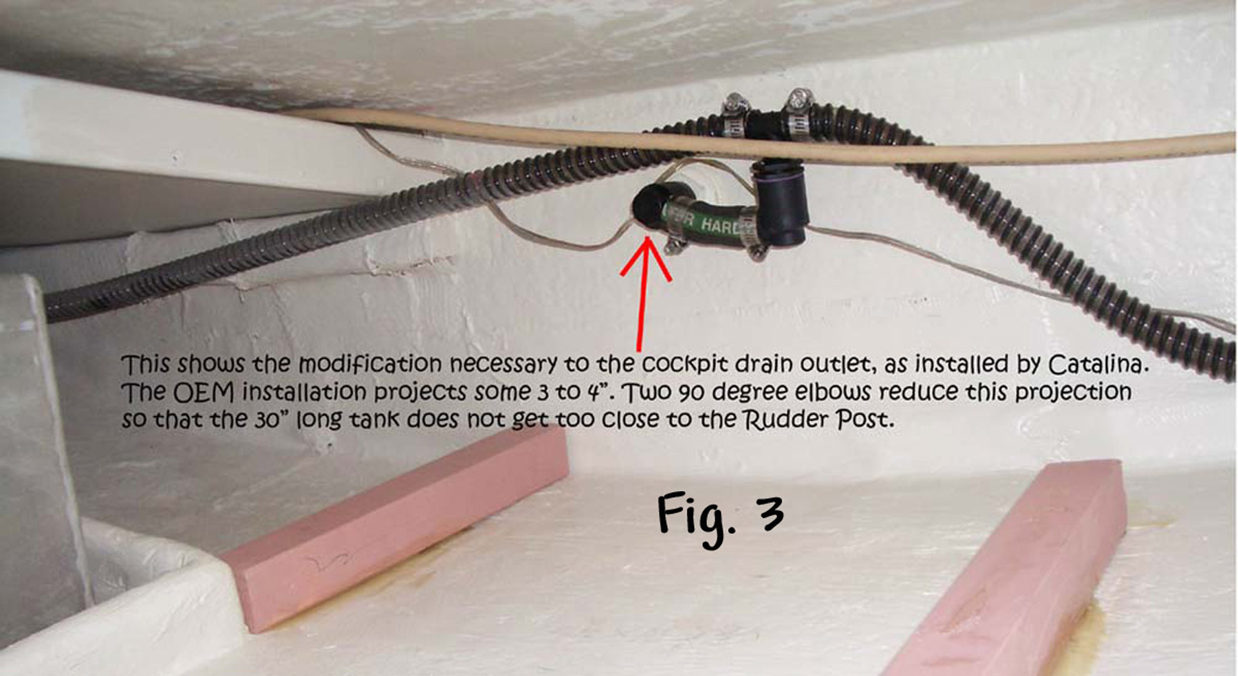
The 20 gallon Todd water tank specified in the bill of materials fits nicely behind the steering quadrant in the stern of the C320. The tank is oriented such that the end with the fittings faces the bow with the feed line fitting down near the hull. The tank is positioned aft such that the rear of the tank touches the transom while on the starboard side the tank is positioned against the edge of the mounting tray for the fuel tank. Unfortunately, the cockpit drain lines protrude into this space. Figure 3 shows the modification needed to move the drain line Tee closer to the transom.

When placing the tank in position, it is easiest to remove the door assembly in the aft stateroom leading to the lazarette. Original plans called for a pressure treated 2 x 2 cut into five sections and cemented to the hull with 3M 5200 adhesive to form a tray that prevents motion of the tank during heeling. This requires that the hull be cleaned and dried in all locations before applying the 5200 adhesive. However, 3M does not market 5200 in Sydney, therefore Bruce fiberglassed in the bearers (Fig. 4). He had to aggressively expose the fiberglass to achieve an adequate bond. Two nylon straps (outboard fuel tank straps) are also fastened to the 2 x 2’s over the top of the tank to further constrain its motion. Note: These straps should be tightened when tank is full. The tank tends to bulge when full and can provide undue tension on the strap fittings if the straps are tightened when the tank is empty. Allow the adhesive securing the 2 x 2’s to the hull to cure overnight before tightening the tank straps.
3. Connecting Fill Line & Vent Line
The fill line for the new tank is Tee’d into the 1½ ” fill line for the existing rear tank near the fill port under the deck at the stern of the boat. This method fills both the existing rear tank and the new tank through the same fitting. Alternatively, an additional fill port can be installed in the deck to allow for separately filling the new tank if desired. The “T” section should be positioned in an upside down manner, as shown in Figure 5, with the main fill line coming in from the top and the fill lines for each rear tank exiting in a horizontal direction. This helps to distribute bleach or other purification liquids to both tanks equally when sterilizing the tanks. An optional ball valve may be installed in the fill line going to the new tank. This would be used to prevent the tank from be filled when the extra capacity or weight is unwanted.


The vent port on deck for the existing rear tank is used to vent the new tank. The vent line for the new tank is Tee’d into the ½ ” line for the existing rear tank near the vent port (Fig. 6). Note: The “T” should be placed as close to the existing port as possible to keep the junction high above both tanks. (Alternatively, an additional vent port can be installed in the deck for separately venting the new tank.)
4. Installing Shutoff Valve and Connecting to Pump
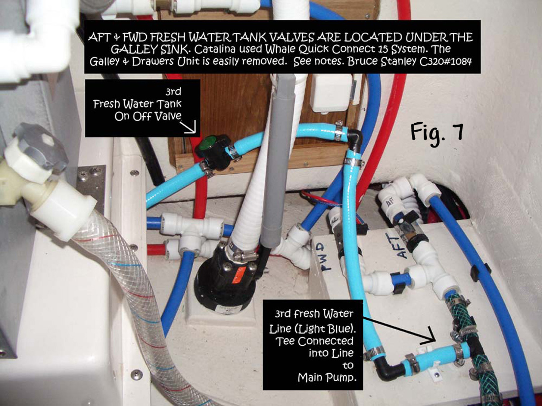
On boats with the tank valves under the galley sink, the 5/8″ feed line is run from the new tank under the rear state-room mattress, under the refrigerator and stove to the pump assembly.
From the lazarette, the new line can be fed through to the space under the rear stateroom mattress. From the rear stateroom the line can be pushed under the refrigerator into the galley area under the stove. In the galley, the new line can be accessed by removing the teak fire extinguisher box from under the stove. From that point, the line can be pulled and run up through the cutout for the galley sink through-hull drain and brought up along side of the existing Whale System valves as shown in Figure 7. (To improve access to this are it is best to first remove the door and drawer console under the sink. Removal of several screws around the perimeter of the console will quickly free the entire assembly for removal.) An inline ball valve is
installed in the vicinity of the existing valves. The Whale component fitting is removed from the SureFlo pump and the blue Whale line is cut after the existing front and rear tanks are joined together. The Whale fitting taken from the pump strainer is reinstalled at this location. (Note:
To remove Whale System fitting, pry cover away from fitting. This removes pressure from collet and allows tubing to slide out. It’s a bit tricky, but easily done once you figure it out. A ½ ” NPT / 5/8″ barb fitting is threaded into the Whale fitting to convert to standard 5/8″ tubing. After the conversion, a small section of 5/8″ tube is cut to fit into the “T” section as shown. The “T” is installed in an upright position with the new tank feed line entering in the bottom. The left side feeds into an elbow located directly over the pump strainer. Make sure you use the elbow so the 5/8″ line does not kink while making the turn into the pump strainer. A SureFlo ½” female thread to 5/8″ barb fitting is used to connect the 5/8″ tube exiting the elbow to the pump. Alternatively, Whale System components can be used for all parts on the feed line.
Boats with the fresh water tank valves under the aft stateroom mattress will have a much easier job of making the connection for the 3rd tank, but the process is the similar.
Concluding Remarks
Aside from the typical contortionist activities required to work on the boat, the installation is fairly easy. When affixing the 2×2’s in place to constrain the tank, make certain they are in the correct position. If using 3M 5200, once it cures, the wood will splinter before the adhesive lets go. Also, use a liberal amount of 5200 and be certain to let it cure overnight before applying any tension.
It should be mentioned that Bill’s original installation did not include the third shutoff valve. Instead, to save time and cost, the feed line from the new tank was Tee’d into the feed line from the existing rear tank. This embodiment failed to work properly because it was difficult to keep the feed line from the new tank below the bottom of the new tank at all points as it traversed the distance to the “T” junction. Therefore, once the existing rear tank drained, the pump pulled in air and failed to completely drain the new tank.
In the USA, you should be able to save many dollars on the purchase of the tank. Defender only charges US$28 to deliver. WM will deliver for nothing with conditions applying. Check with them.
If you can purchase Whale Quick Connect hose and fittings, do so. They have been used by Catalina and look cost effective and efficient. These will be used under the sink (not in the Lazarette Vent parts).
Flexible Tank vs. Solid Tank: I gave this a lot of thought and am pleased with my decision on the Todd tank. This 20 gallon tank fits perfectly into the best available position.
Parts List:
- Todd 20 gal tank (85-1666W) $86 @ Defender, $105 @WM
- Todd Angle Fittings Kit (93-2223) $13 @ Defender, $16 @ WM
- ½ inch plastic plug for sealing off unwanted vent outlet on Todd tank
- 10’ of treated 2×2 DAR bearer timber (about AU$15)
- 3 saddles for installing straps to secure tank (about AU$3 each)
- 3½ meters of strap material
- 1½ inch Fill Hose (AU$35) note: I think you only need 10’ (check it)
- 1½ inch Tee (AU$10) 1½ inch ball Valve (AU$28) plus 2 connectors (AU$10) Optional
- ½ inch hose for vent & feed lines (AU$30) note I think it was 10mtrs long. Check it.
- 1 fiberglass kit (AU$30) plus extra Matting and Resin and Catalyst (AU$35)
- 1 Heavy Duty Scraper to remove Flowcoat to fiberglass bearers in (AU$36)
- 1 Tube Sikaflex White (AU$19)
- Teflon tape $1
- 4 elbows (½ inch) – two under sink and two for cockpit drain adaptation (appox $12)
- 2 of ½ inch Tee joints (AU$6) – one for the connection under the sink and one for the Vent line
- ½ inch bronze tail (AU$10) outlet on Todd tank (or use plastic one from Todd Kit)
- 16 of ½ inch S/S hose clamps (AU$48)
- 6 of 1 inch S/S hose clamps (AU$28)
- ½ inch Valve to turn on/off Feed Line (under sink)